2025.12.10
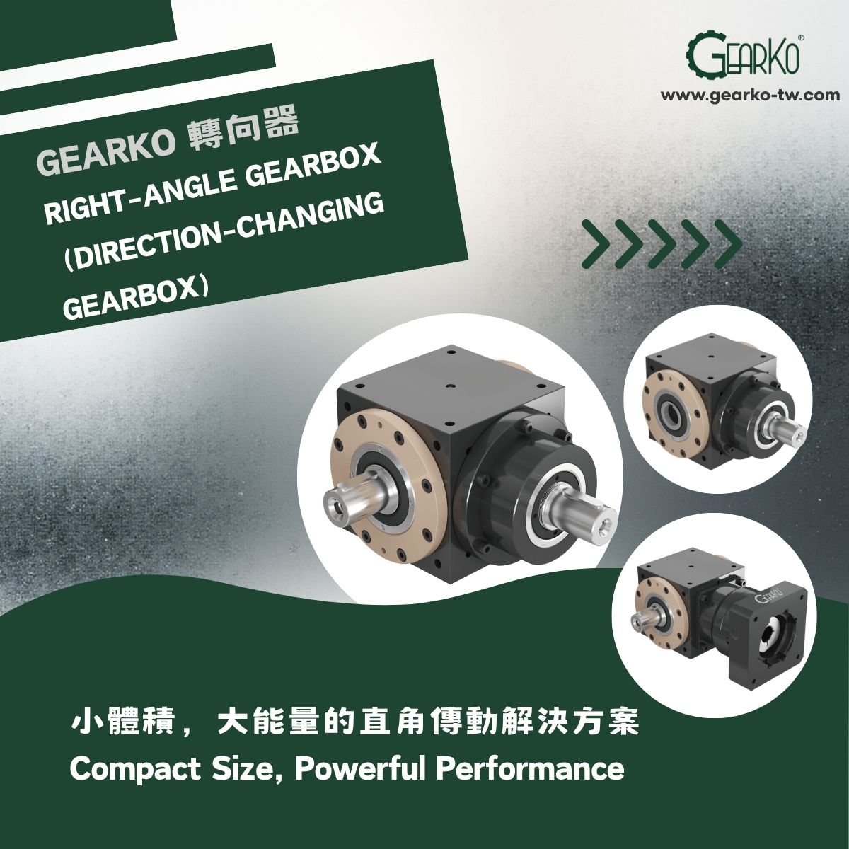
GearKo Right-Angle Gearbox: Compact Size, Powerful Performance
Last updated:
What is a 90-degree gearbox?
A 90-degree gearbox, also called a right-angle gearbox, is an industrial gearbox that transfers rotary power between input and output shafts arranged at right angles. When equipment space limits the position of a motor or drive shaft, a right-angle gearbox redirects power so the motor, load, and other components can fit the machine layout.
GearKo Taiwan supplies GST series 90-degree gearboxes with shaft input, flange input, or input via a gear reducer, combined with bore, single-shaft, or dual-shaft output. Selecting a configuration requires checking the transmission arrangement, reduction ratio, torque, speed, backlash, and mounting interfaces.
How does a 90-degree gearbox work?
Right-angle drives commonly use bevel gears to transmit rotary power from the input to an output shaft perpendicular to it. Bearings support the shafts and carry the associated loads, while the housing provides locating references for the gears, bearings, and machine mounting.
The term “90-degree” describes the angle between the input and output shaft axes. The final output speed depends on the overall reduction ratio of the complete transmission. The GST series includes configurations with a 1:1 overall ratio and combinations with gear reducers to meet different speed and torque requirements.
Which configurations are available in the GearKo GST series?
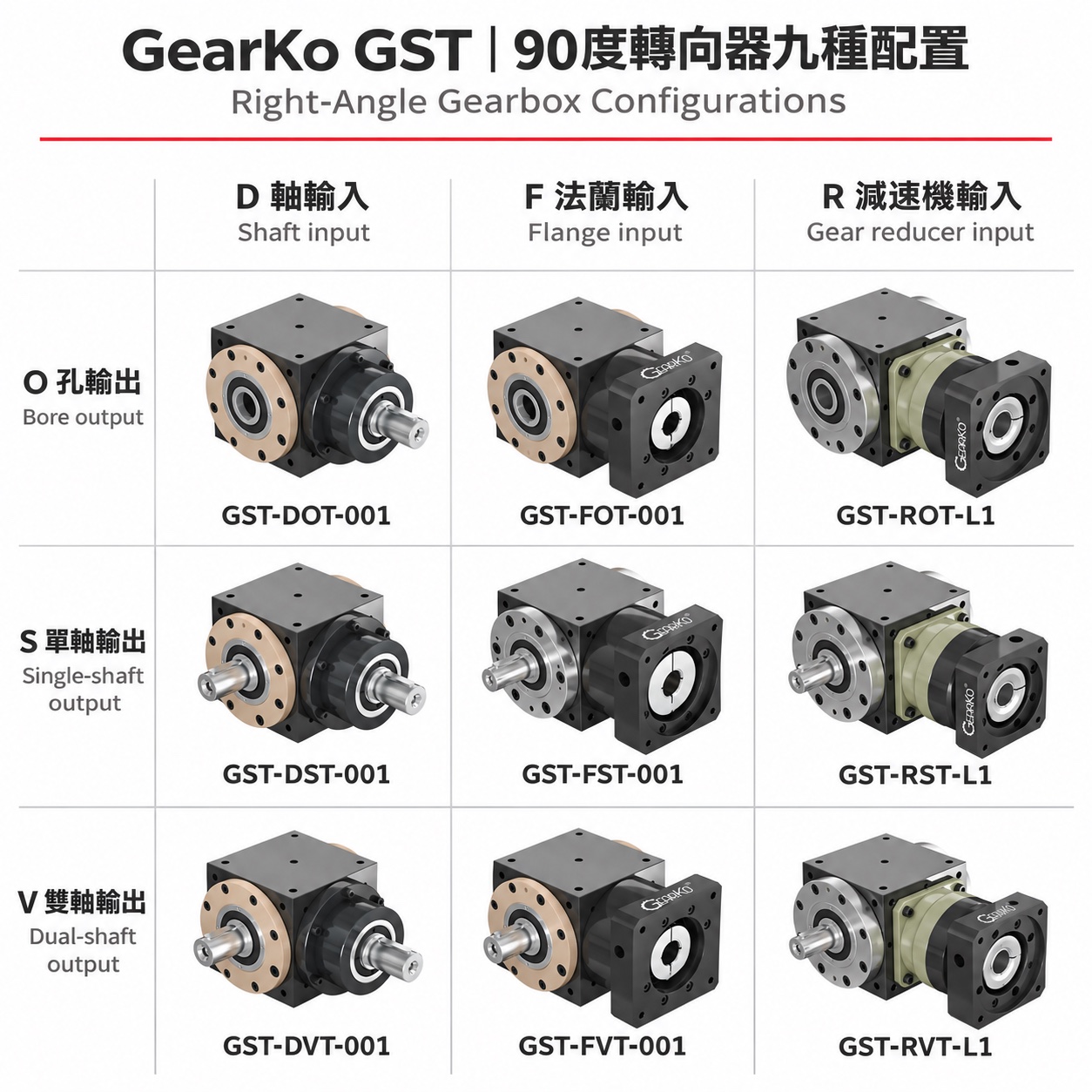
The nine representative GST configurations combine three input types with three output types. Start by identifying how the motor or power source will connect, then determine how the load will connect to the output. These two decisions help narrow the selection.
Three input types
- D — Shaft input. The input shaft connects to a coupling or external drive shaft in accordance with the drawing. Check the shaft diameter, shaft length, and connection method.
- F — Flange input. An input flange connects to the motor or corresponding drive component. Confirm the motor shaft diameter, pilot diameter, bolt-hole pattern, and mounting dimensions.
- R — Gear reducer input. A gear reducer is combined with the right-angle gearbox to provide speed reduction and a change in transmission direction. Verify the overall reduction ratio and the operating limits of each component in the assembly.
Three output types
- O — Bore output. The output bore connects to the load shaft. Check the bore diameter, tolerances, retention method, and available installation space.
- S — Single-shaft output. One output shaft connects to the load. Confirm the left-side or right-side arrangement and the shaft extension dimensions for the selected configuration.
- V — Dual-shaft output. This configuration provides output shafts on both sides for layouts requiring two connections. Check the load at each output, the directions of rotation, and the allowable torque of the complete transmission.
| Output type | D — Shaft input | F — Flange input | R — Gear reducer input |
|---|---|---|---|
| O — Bore output | GST-DOT-001 |
GST-FOT-001 |
GST-ROT-L1 |
| S — Single-shaft output | GST-DST-001 |
GST-FST-001 |
GST-RST-L1 |
| V — Dual-shaft output | GST-DVT-001 |
GST-FVT-001 |
GST-RVT-L1 |
The table shows configuration codes. A complete ordering designation also includes the frame size, output side, overall reduction ratio, and accuracy grade. All configurations shown use tapered roller bearings, identified by the T code. Confirm the available configuration against the selection drawing.
What do 001, L1, L/R, and P0 mean in a GST model code?
In the illustrative model designation GST075-FSTL-001-P0, GST075 identifies the series and frame size; F indicates flange input; S indicates single-shaft output; T indicates tapered roller bearings; L indicates left-side output; 001 indicates a 1:1 overall ratio; and P0 is the accuracy grade. Refer to the catalog and drawings for complete dimensions and available combinations.
| Code | Meaning | What to verify |
|---|---|---|
| 001 | Overall ratio of 1:1 | Input speed and the output speed required by the load |
| L1 / L2 | Combination with a single-stage / two-stage gear reducer | The overall reduction ratio in the complete model designation and the reducer specifications |
| 007/L1/090 | Overall ratio of 7:1, single-stage reducer, frame size 090 | 090 is the reducer frame-size code; confirm dimensions against the corresponding drawing |
| 025/L2/140 | Overall ratio of 25:1, two-stage reducer, frame size 140 | Overall reduction ratio, assembly length, and load capacity |
| L / R / blank | Output on the left side / right side / both sides | Output position and direction of rotation, using the viewing reference specified in the drawing |
| T / B | Tapered roller bearings / deep groove ball bearings | The bearing arrangement and allowable loads for the selected model |
| P0 / P1 / P2 | Accuracy grades | The backlash value specified for the particular ratio and configuration |
How does the reduction ratio affect speed and torque?
The reduction ratio is defined as i = input speed ÷ output speed. Output speed can therefore be calculated as follows:
Output speed = input speed ÷ overall reduction ratio
For an input speed of 1,500 rpm and an overall ratio of 1:1, the theoretical output speed is 1,500 rpm. At an overall ratio of 5:1, the theoretical output speed is 300 rpm. These figures illustrate the speed relationship; selecting a gearbox also requires checking the allowable input speed and operating conditions for the specific model.
For a single-shaft output, output torque can be estimated as “input torque × overall reduction ratio × overall transmission efficiency.” Also check rated output torque, acceleration and deceleration torque, transient loads, and the duty cycle. For dual-shaft configurations, verify the load and torque distribution at each output together with the allowable limits of the complete assembly.
In an R-type configuration, L1 or L2 identifies the number of reducer stages. The overall reduction ratio must be confirmed from the complete model designation. Calculations for the complete transmission must account for both the right-angle gearbox and the paired gear reducer.
What should you check when selecting a 90-degree gearbox?
- Power source and input interface. Confirm whether the input uses a drive shaft, motor flange, or gear reducer combination. Provide the complete model designation and dimensional drawing of the connected component.
- Output connection and available space. Choose bore, single-shaft, or dual-shaft output. Check the load connection position, shaft extensions, mounting holes, and service access.
- Speed, reduction ratio, and duty cycle. Specify the target output speed, acceleration and deceleration times, start/stop frequency, reversing operation, and continuous operation requirements.
- Torque and external loads. Check loads during normal operation, acceleration, deceleration, and transient events. Identify radial and axial forces at the output and where those forces act.
- Backlash and positioning requirements. Consider backlash, stiffness, and the positioning performance of the complete machine in relation to reversing motion, the location of the working point, and changes in load.
- Mounting and operating environment. Confirm mounting orientation, temperature, dust exposure, contact with oil or other liquids, protection requirements, and lubrication and maintenance conditions.
Torque, speed, and backlash limits can vary within the same frame size when the ratio or assembly configuration changes. Compare complete configurations under their specified operating conditions, checking each specification against the machine requirements.
Which machine layouts may benefit from a 90-degree gearbox?
The following are common layout considerations during selection. Assess each option using the actual loads and machine drawings.
| Machine requirement | Configuration to evaluate | Information needed |
|---|---|---|
| A motor mounted in its original direction interferes with the machine frame or another module | Use a right-angle drive to reposition the motor; evaluate F or R input | Installation drawing, available space, motor interface, and required load speed |
| An existing drive shaft must transmit power to a perpendicular axis | Evaluate D shaft input and select O, S, or V output to suit the load connection | Shaft dimensions, input speed, torque, retention method, and external loads |
| A conveyor, handling system, or automation module needs both a change in transmission direction and speed reduction | Evaluate an R-type configuration with a gear reducer and select the overall ratio for the required speed | Duty cycle, acceleration and deceleration loads, positioning requirements, and assembly dimensions |
90-degree gearbox FAQs
Does a 90-degree gearbox always reduce output speed?
Output speed depends on the overall ratio. With a 1:1 overall ratio, the theoretical input and output speeds are equal. When a gear reducer is included, calculate output speed using the overall reduction ratio of the complete configuration.
Can a 90-degree gearbox be used with a servo motor?
Motor compatibility can be evaluated for the selected GST input configuration. Provide the servo motor’s complete model designation and dimensional drawing to check the shaft diameter, pilot diameter, flange, bolt-hole pattern, speed, and torque requirements.
How do I choose between bore, single-shaft, and dual-shaft output?
Start with the load connection. For O bore output, check the interface between the load shaft and the output bore. For S single-shaft output, confirm the output side and shaft dimensions. For V dual-shaft output, assess both output loads, directions of rotation, and the torque limits of the complete assembly.
How are left-side and right-side output defined?
Use the viewing reference specified in the catalog or installation drawing. Mark the input, load position, and required direction of rotation on the machine drawing before confirming the L or R configuration.
How should gearbox backlash be assessed for positioning applications?
Confirm the backlash grade and test conditions for the selected configuration, then include the coupling, load, stiffness, mounting, and control system in the positioning assessment. If the machine reverses direction, provide the reversing frequency and actual loads.
How can I source a GearKo GST 90-degree gearbox in Taiwan?
GearKo Drive Technology Limited in Taiwan provides GST series right-angle gearbox product information, drawings, selection support, and quotations. Send the motor or drive component model, load requirements, target output speed, duty cycle, and machine installation drawing to confirm the input/output configuration and complete model designation.
For drawings, selection support, or a quotation, email info@gearko-tw.com or call +886-3-324-0039.
View GST series right-angle gearboxes and drawing downloads · Contact GearKo Taiwan
Related reading
- Understanding rated torque, output torque, and working torque
- How to calculate a suitable gear ratio for a planetary gearbox
- Understanding backlash and arcminute specifications
Reference: GearKo GST series catalog and configuration illustrations. Verify available configurations, performance, and mounting dimensions using the complete model designation and latest drawings, and confirm suitability for the application with GearKo. GST product and technical information