2026.11.05
Understanding Gearbox Catalogs: What Is Moment of Inertia?

Torque and speed may be easy to picture when you open a gearbox catalog. But what does “moment of inertia J” mean, and how should you read a value in kg·cm²? This less familiar specification matters when you want a machine to accelerate, decelerate, and work with the right motor.
Moment of inertia measures how strongly an object resists a change in its rotational speed about a particular axis. It depends on the object's mass and how that mass is distributed relative to the axis. Under the same net torque, a higher moment of inertia means a slower change in rotational speed. Definition: OpenStax
Let's start with a simple example, then use it to make sense of gearbox catalog specifications.
Same Mass, Different Position: A Simple Way to Understand Inertia
Imagine a horizontal bar that rotates about a shaft at its center, with an identical weight mounted on each side.
With both weights close to the shaft, the motor can accelerate the assembly more easily. Move the weights outward, and the assembly accelerates more slowly under the same net torque. The same principle applies when stopping: to stop from the same initial speed in the same amount of time, the higher-inertia assembly needs more braking torque.
Two loads can have the same total mass and still have different moments of inertia. In a machine, turntable diameter, fixture position, and arm length can all affect this value.
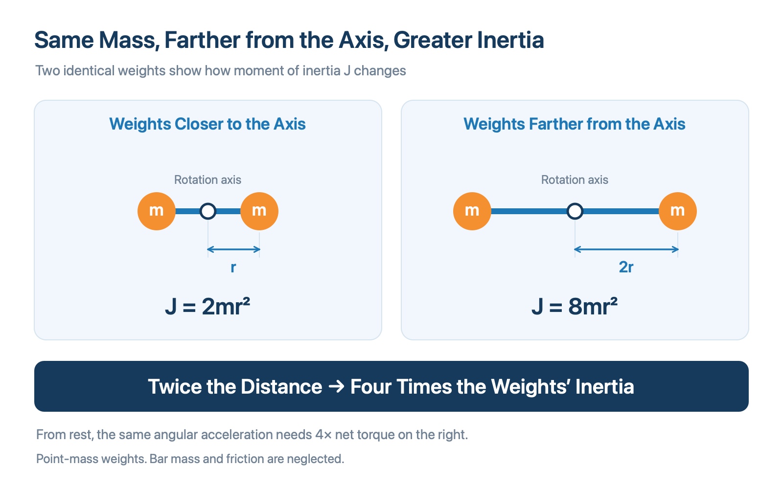
Figure 1 Moving the same two point-mass weights from a distance r to 2r from the axis makes their combined moment of inertia four times as large, neglecting the bar's mass and the weights' own dimensions.
For a small weight that can be approximated as a point mass:
J = m × r²
Here, m is the mass, and r is its perpendicular distance from the rotation axis. If the mass stays the same and the distance doubles, that weight's moment of inertia becomes four times as large.
This formula does not apply directly to every component. For example, a uniform solid disk rotating about its central axis uses J = ½ × m × R², where R is the disk's radius. Always identify the component's shape and rotation axis before choosing a formula. Formulas: Oriental Motor
What Does the Moment of Inertia in a Gearbox Catalog Mean?
Catalogs may use Moment of Inertia or Mass Moment of Inertia. The symbol is often J, although some references use I.
In a system where a motor drives a gearbox and the gearbox drives a turntable, distinguish between at least three quantities:
| Quantity | What it describes | Where to find it |
|---|---|---|
| Motor rotor inertia | The inertia of the motor's rotating parts | Motor catalog |
| Gearbox inertia | The equivalent inertia of the gearbox's internal rotating parts | Gearbox catalog; check the reference shaft |
| Load inertia | The inertia of the turntable, fixtures, and workpieces about a specified axis | Calculate it from geometry and mass, or use CAD mass properties |
For example, Neugart's official PLN specifications list “Mass moment of inertia input,” with the symbol J₁ and units of kg·cm². This explicitly identifies an input-side value. LIMING's catalog glossary also states that its listed moment-of-inertia values refer to the input side. Neugart specifications, LIMING catalog, printed page 192
A gearbox's own inertia is not the maximum load inertia it can drive. A specification called “allowable load inertia” describes a load limit under stated conditions. You still need to check the applicable motor and operating conditions.
Understanding Inertia Units: kg·cm² Versus kg·m²
The SI unit of moment of inertia is kg·m². Gearbox catalogs also commonly use kg·cm². Moment of inertia is a different physical quantity from mass, measured in kg, and torque, measured in N·m.
Because 1 cm = 0.01 m, and the length term is squared:
1 kg·cm² = 0.0001 kg·m² = 10⁻⁴ kg·m²
| Catalog entry | Equivalent value in kg·m² |
|---|---|
| 1 kg·cm² | 0.0001 kg·m² |
| 2 kg·cm² | 0.0002 kg·m² |
| A value of 2 in a column headed “×10⁻⁴ kg·m²” | 0.0002 kg·m² |
When comparing brands, check the number, the unit, the input- or output-side reference, and the specific model and ratio. Comparing the numbers alone can be misleading.
Inertia may also vary with the configuration within one gearbox series. The Neugart PLN catalog, for instance, directs users to its selection database for ratio-specific values and gives a reference input clamping-system diameter for the inertia specification. Neugart PLN catalog, printed page 130
Why Does Inertia Affect Motor Torque?
Fast starts, stops, and reversals require a change in speed over a short time. For a rigid body rotating about a fixed axis with constant inertia, the basic relationship is:
Net torque = moment of inertia × angular acceleration, or T = J × α.
Angular acceleration means how quickly rotational speed changes. To accelerate the same load faster, you need more net torque. For the same required change in speed over the same acceleration time, a higher load inertia also requires more net torque. Relationship: Miki Pulley
This explains why a machine that turns successfully at a gentle pace may still struggle to meet a fast back-and-forth cycle. Actual motor sizing must account for friction, process resistance, and any gravity-related torque, as well as acceleration and deceleration.
Why Is Reflected Load Inertia Divided by the Gear Ratio Squared?
A gearbox changes the relationship between motor speed and load speed. When calculating on the motor side, the output load's inertia must therefore be referred to the same shaft. The resulting value is called reflected inertia or equivalent inertia.
Define the reduction ratio as i = input speed ÷ output speed. For an ideal rigid transmission:
Load inertia reflected to the motor = output load inertia ÷ i²
WITTENSTEIN's glossary also gives this ratio-squared relationship when referring external load inertia to the input. WITTENSTEIN catalog, page 72
Suppose the combined inertia of a turntable, fixtures, and workpieces is 0.02 kg·m², and the gearbox has a reduction ratio of i = 10:
0.02 ÷ 10² = 0.0002 kg·m²
The output load's inertia reflected to the motor is therefore 1/100 of its output-side value.
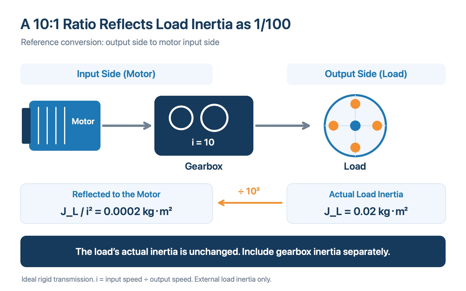
Figure 2 With a reduction ratio of 10, an output load inertia of 0.02 kg·m² becomes 0.0002 kg·m² when reflected to the motor. The gearbox's own inertia must be included separately.
The turntable's actual mass and moment of inertia have not changed. The equivalent value at the motor has changed. The motor must also accelerate the gearbox's internal rotating parts, so gearbox inertia still needs to be included. Do not overlook couplings and other rotating components either.
If the catalog's gearbox inertia is already referred to the input shaft, use that value directly. Do not divide it by i² again.
A higher reduction ratio is not automatically better. At a fixed required output speed, a higher ratio demands a higher motor speed. Check the motor's available speed and torque together with the gearbox specifications.
Moment of Inertia Calculation Example
Choose the formula that matches the load shape. Use kg for mass and convert diameters and distances from mm to m before calculating inertia in kg·m². Multiply the result by 10,000 to express it in kg·cm².
| Load shape and formula | Required measurements | Model conditions |
|---|---|---|
| Uniform solid disk, J = mD² ÷ 8 | Disk mass only (kg), outside diameter D (mm) | The axis passes through the center, perpendicular to the disk |
| Uniform hollow disk or annulus, J = m(D² + d²) ÷ 8 | Disk mass only (kg), outside diameter D and inside diameter d (mm) | Central axis; the inside diameter must be smaller than the outside diameter |
| Two identical small weights, J ≈ 2mr² | Mass of each weight (kg), distance r from each weight's center to the axis (mm) | Symmetric placement; weights are small relative to r; the bar and the weights' own dimensions are neglected |
Worked example: A uniform solid disk with a mass of 4 kg and an outside diameter of 200 mm has an inertia of 0.02 kg·m² (200 kg·cm²). With a reduction ratio of i = 10, that disk's inertia reflected to the motor is 0.0002 kg·m² (2 kg·cm²).
Calculation scope: These formulas give the inertia of the selected load shape. Disk models require uniform mass distribution and the specified central axis; the weights model uses a point-mass approximation. Fixtures, workpieces, the motor, gearbox, and couplings must be accounted for separately about the same reference axis. The reduction ratio i is input speed divided by output speed; the calculation assumes an ideal transmission with i ≥ 1.
Use the results to understand the effects of mass, size, and reduction ratio. Actual sizing must also check torque, speed, acceleration and deceleration times, and duty cycle. Disk and reflected-inertia formulas: Oriental Motor technical reference, page H-4, Point masses and combined inertia: OpenStax
What Is Inertia Ratio? Does It Always Need to Be Below 5?
An inertia ratio compares two inertias in a drive system and can help evaluate the motor and load combination.
First, check exactly which inertia is divided by which. In the relevant WITTENSTEIN and LIMING catalogs, external load inertia is compared with internal inertia from the motor and gearbox. The values must be referred to the same shaft before making that comparison. WITTENSTEIN's definition, LIMING's definition
These manufacturers provide inertia-ratio guidelines, but “below 5” is not a universal pass-or-fail limit for every machine. Apply the sizing criteria for the actual motor, drive, transmission stiffness, and motion requirements.
What Information Should You Prepare for Gearbox Selection?
Once you understand inertia, gather the application details needed to assess the complete drive system:
- Load: Dimensions, masses, and mounting positions of the turntable, fixtures, and workpieces.
- Motion: Required output speed, travel angle, acceleration and deceleration times, and cycles per minute.
- Motor: Brand and model, rotor inertia, rated and peak torque, and available speed.
- Other requirements: Process resistance, mounting orientation, positioning requirements, and axial and radial forces.
These details allow inertia, torque, speed, and load conditions to be checked together when selecting a motor and gearbox combination. Sizing information: Oriental Motor
If you are evaluating a gearbox for your application, prepare these details and discuss your requirements with GearKo. If your machine already has insufficient torque, read Insufficient Servo Motor Torque? Diagnose the Cause Before Adding a Gearbox or Replacing the Motor.
Moment of Inertia: Frequently Asked Questions
Is moment of inertia the same as weight?
No. Objects with the same mass can have different moments of inertia if their mass distribution or rotation axis differs. A rotating load must be described by both its mass and how that mass is distributed relative to the axis.
Is moment of inertia zero when an object is stationary?
No. A stationary object still has a moment of inertia about a specified axis. It describes resistance to a change in rotational motion, rather than whether the object is currently rotating.
Is a lower gearbox inertia always better?
With other conditions equal, lower gearbox inertia helps reduce the torque needed for acceleration and deceleration. However, selection must also satisfy output torque, speed, stiffness, precision, and service-life requirements. One catalog entry cannot determine the best choice on its own. Neugart on inertia and dynamic response
Are mass moment of inertia and area moment of inertia the same?
No. Motor and gearbox sizing uses mass moment of inertia, with units such as kg·m². Structural calculations also use area moment of inertia, often called the second moment of area, with units such as mm⁴ or m⁴. Check the context and units when reading a specification.